Preparing
3D printing of the housing and button holder
Initially, a 3D printer was tasked with printing individual components. The components were previously designed and can also be customized individually as needed.
Modification of the lamp socket with integrated LED
While the individual parts were being printed, the assembly of the system was started. For this purpose, the circuit board of the lamp socket with integrated LED for the illuminated push button had to be modified because the LED was designed for 24 V in the previous configuration. However, the illuminated push button is supposed to be connected to the Raspberry Pi, which only supplies 3.3 V or 5 V. The LED is operated at 3.3 V in this case. The original circuitry is bridged using a wire and an appropriate series resistor. The required series resistor could be calculated using the forward voltage and the desired current through the LED. For a white LED, the forward voltage is typically around 3.2 V. To allow the LED to shine as brightly as possible while ensuring a long lifespan, the current was limited to 15 mA. The series resistor could now be calculated using the following equation:
Rv = (Uq-UD)/I = (3.3 V - 3.2 V)/0.015 A = 6.67 Ω
Since the calculated value is not a standard value for a series resistor, the next larger available value of 10 Ω was chosen. A picture of the modified circuit board is shown in Figure 1.
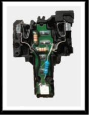
Figure: Integration of a pull-up resistor for the acknowledge button, from Kai W.
To ensure that the input pin of the Raspberry Pi is set to a defined state when the button is not pressed, a pull-up or pull-down resistor is necessary. Without such a resistor, the input pin can be in a "floating" state, meaning it is neither defined as HIGH nor LOW. This can result in malfunctions. In this project, a pull-up resistor is chosen, which is also the most common option in practice, as it references the switch to GND, reducing susceptibility to interference. The resistor is typically sized at 10 kΩ. According to Ohm's law, this results in a small current of 0.33 mA in the idle state with a supply voltage of 3.3 V. While using an even larger resistor would further reduce power consumption, it can introduce errors due to a voltage divider effect between the pull-up resistor and the contact resistance of the pin if the resistor is too large.
To avoid using an additional breadboard, the pull-up resistor was soldered directly between the wires and insulated with heat shrink tubing. The result is shown in Figure 2. The heat shrink tubing was then applied and properly secured using a heat gun in the next step.
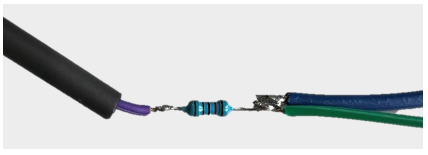
Figure: Integration of the pull-up resistor, from Kai W.