Mission
THE MISSION

source: pixabay.com
The objective of the project is to determine the energy consumption of a model plant using an energy meter from Phoenix Contact, analyze the measurement values using the AXC F 3152 controller and the AI extension module AXC F XT ML 1000, and write them to a database for clear visualization. For this purpose, a control cabinet will be created to control the model conveyor belt and a combination of CEE and Schuko sockets.
The operational states of the conveyor belt, the CEE and Schuko sockets, as well as any faults, will be indicated through illuminated push buttons or indicator lights. Additional consumers can be connected through the CEE and Schuko sockets to generate new consumption measurements. The goal is to present the energy consumption in a comprehensible manner and analyze it using AI.
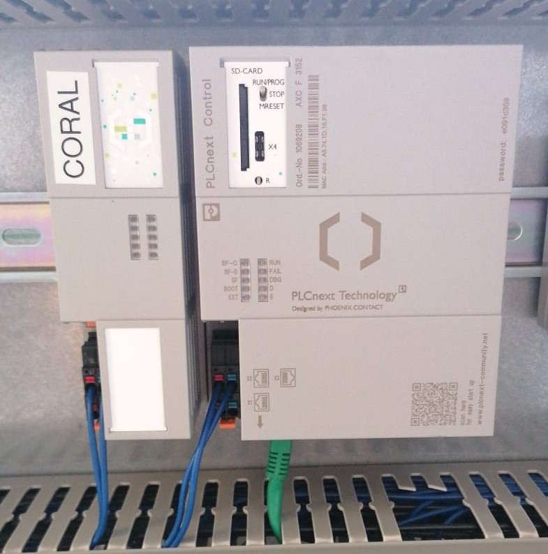
Figure: AXC F 3152 controller and the AI
extension module AXC F XT ML 1000
INFORMATION PHASE
An initial joint project discussion took place. The following wishes were expressed by the team:
- An existing control cabinet is to be used for setting up the system.
- The model conveyor belt should be designed to be switchable in order to function as the basic consumer of the model conveyor belt system. In addition, the operating status of the conveyor belt is to be displayed.
- In case of tripping of the motor protection switch, the system shall indicate a fault. After the fault has been rectified, the conveyor belt shall not restart automatically.
- The system must be able to be switched on and off completely. After a voltage supply or a mains failure, a new acknowledgement must take place.
- A signal lamp shall indicate whether the control voltage is present.
- Additional consumers shall be designed to be switchable via a CEE earthed socket combination and their operating status shall be displayed.
- The energy consumption of the plant is to be measured and the measured values of the energy measuring device are to be stored in an InfluxDB database.
- The meausered data will be analysed by an AI and identifies faulty measurements are identified
- The responsible person should get a message over the faulty measurement.
PLANING PHASE

source: pixabay.com
During the information phase, research was conducted on the operation and measurement capabilities of energy meters from Phoenix Contact. Data sheets of various models were studied and reviewed for the planning phase. Additionally, information was gathered on how to retrieve the measurement values from the energy meter. The Phoenix's proprietary "EMpro REST API" was utilized, which demonstrates how the measurement values can be read in a custom program using a simulated meter.
For communication with the database, the system needs to be connected to the internet. Therefore, the control cabinet must be equipped with a router. The router was provided by the BBS2 Wolfsburg, requiring only the identification and study of its data sheet. The router is intended to handle two networks: the internal (LAN) and external (WAN) networks. These networks should have different IP address ranges. Fixed IP addresses will be assigned to participants via the internal network, while the router will obtain an IP address through DHCP via the external network to access the internet.
After conducting some research, we came across the EEM-MA770, a multifunctional energy meter designed for front panel mounting. The EEM-MA770 offers a wide range of measurement capabilities. It can measure currents, voltages, powers, as well as the phase shift angle (φ) between current and voltage, and the total harmonic distortion (THDI). The measurement capabilities are extensive. The "EMpro REST API" was particularly crucial in selecting this meter, as it provides detailed instructions on how to retrieve measurement values from external software.
To meet the team's requirements, we considered the components needed for the control circuit. For acknowledgment, a safety relay with an emergency stop function and a blue illuminated push button are required. Additionally, a 22E auxiliary contactor is needed to power on and off the system and provide control voltage. Furthermore, I contemplated displaying the operational state of the model conveyor belt and the socket combination differently. One will be indicated using illuminated push buttons, while the other will be displayed using indicator lights. Auxiliary contacts for the motor protection circuit breaker are necessary to control the indicator light and interrupt the holding circuit of the main power contactor for the motor when it trips. The main power contactors will be self-holding, so auxiliary contacts are required.
The use of "E-PLAN Education"
facilitated the design of circuit diagrams, assembly plans, and the layout of
the control cabinet door. It allowed for the arrangement of components and
positioning of control elements on the control cabinet door to be planned
effectively.
THE FUCTIONS OF THE HARDWARE
The control voltage to the fuses -F6/-F7 is only enabled through contacts 43/44 of the auxiliary contactor -K0 when the "System On" button -S1 is pressed, thus turning on the system. The illuminated push button -S1/-P1 "System On" lights up, and the auxiliary contactor -K0 remains latched in the activated state. Using -S0 "System Off" interrupts the latching of -K0, thereby shutting down the system.
Once the control voltage is applied, the indicator light -P6 "Control Voltage On" illuminates to indicate to the operator that the system is supplied with voltage. Similarly, the illuminated push button -P7 "Acknowledge" illuminates, as the normally closed contacts 41/42 of the safety relay -F9 are not yet activated. The illuminated push button goes out when the system is turned on, the emergency stop -S8 is not pressed, and "Acknowledge" is pressed using -S7. Now, the system is ready for operation.
The normally closed contacts 13/14 of the safety relay -F9 are activated once it is acknowledged. Additionally, the control voltage for the circuit of the main contactors -Q1 and -Q2 is released. Pressing the -S2 "Motor Start" button activates the latching of the main contactor -Q1, the indicator light "Motor On" -P8 starts to illuminate, and the motor starts rotating. Pressing -S3 "Motor Off" interrupts the latching of -Q1, causing the motor to stop and -P8 to extinguish. Additionally, in the coil circuit of the contactor -Q1, there is a normally closed contact 33/34 from the auxiliary contact module of the motor protection circuit breaker -F1. This contact is used to interrupt the latching of -Q1 in case of a fault. It also prevents the motor from automatically restarting after the motor protection circuit breaker is reactivated.
The latching of the main contactor -Q2 is activated through the illuminated push button -S4/-P4 "Socket On", causing the indicator light of the illuminated push button "Socket On" -P4 to start illuminating, and the voltage for the CEE-Schuko socket combination is released. Pressing the illuminated push button -S5/-P5 "Socket Off" interrupts the latching of -Q2, thereby disconnecting the power supply to the CEE-Schuko socket combination. The indicator light of the illuminated push button -S5/-P5 is triggered by the normally open contacts 31/32 of the main contactor -Q2 to indicate that no voltage is present at the sockets.
After the control cabinet was properly wired, some covers for the cable duct had to be newly fabricated as they were missing. While my team partner was dealing with the power supply of the control cabinet, I installed the CEE-Schuko socket combination and the connector for the model conveyor belt. Furthermore, the supply line and motor connection were made using a Harting connector. On the motor terminal block, I swapped Phase L3 with Phase L1 because the motor, due to the reversing effect of the gearbox, otherwise would it rotate in counterclockwise direction with the normal phase sequence.
Following are some pictures for your first impression:
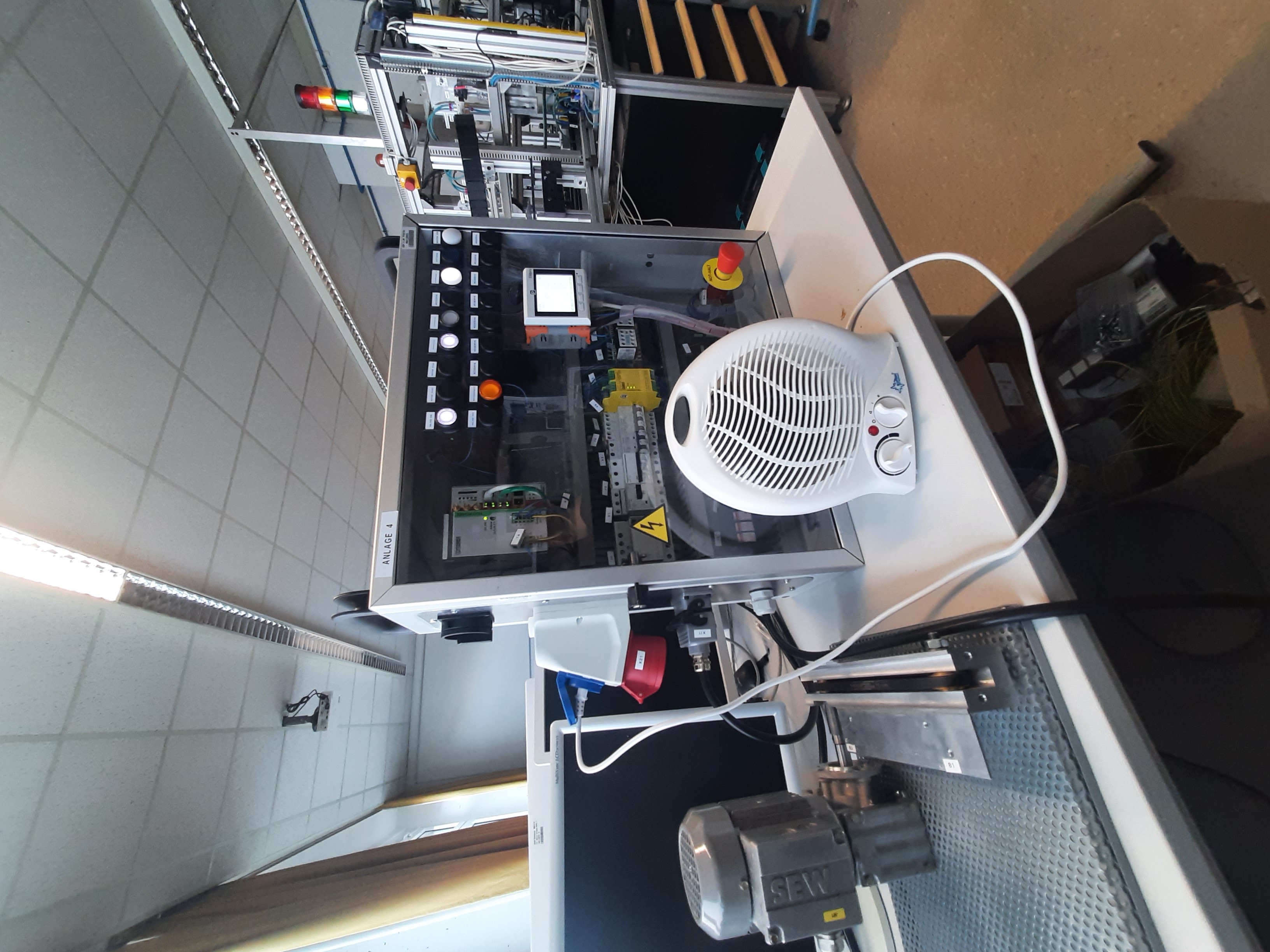
Figure: control cabinet with consumers
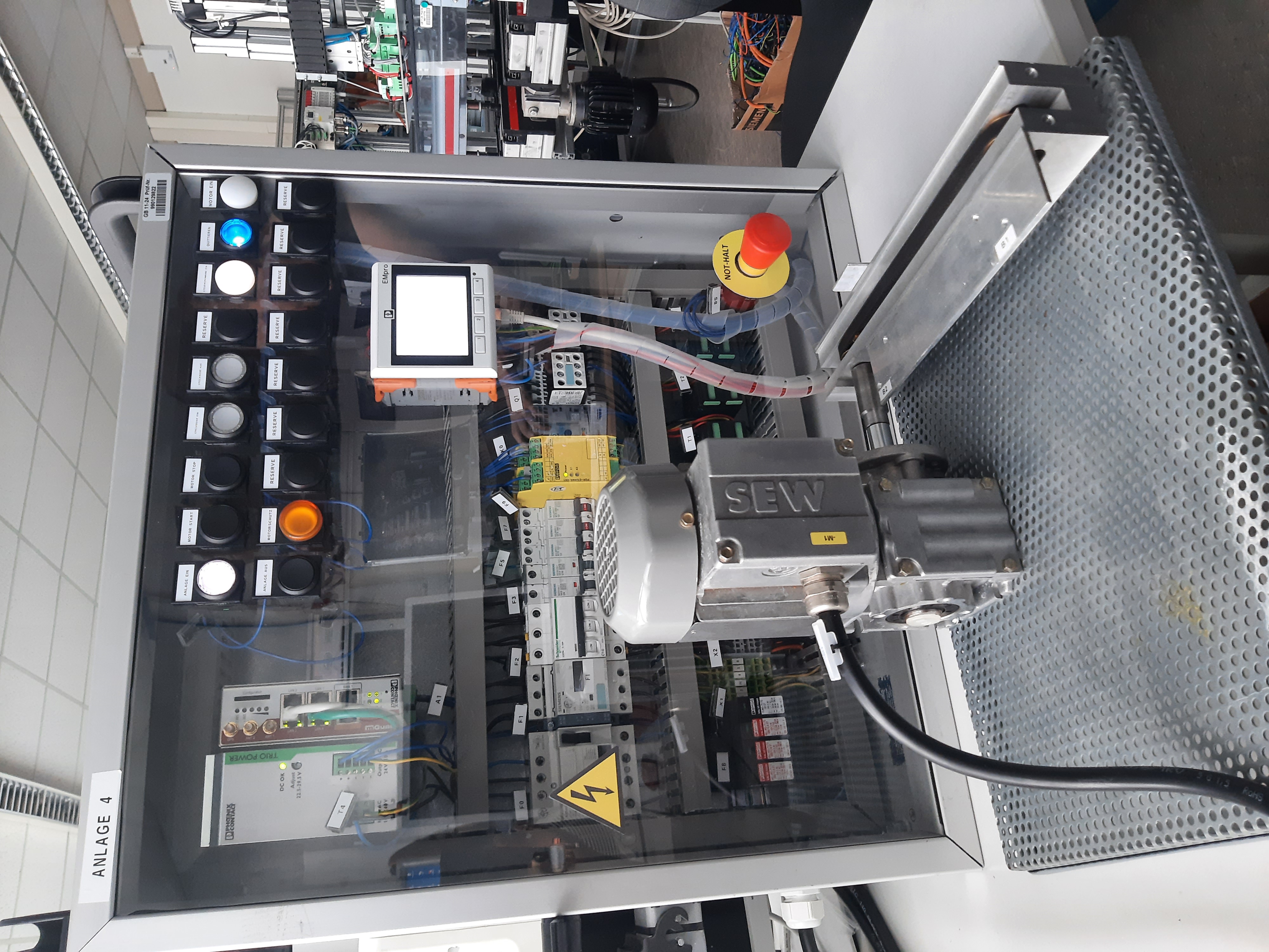
Figure: control cabinet
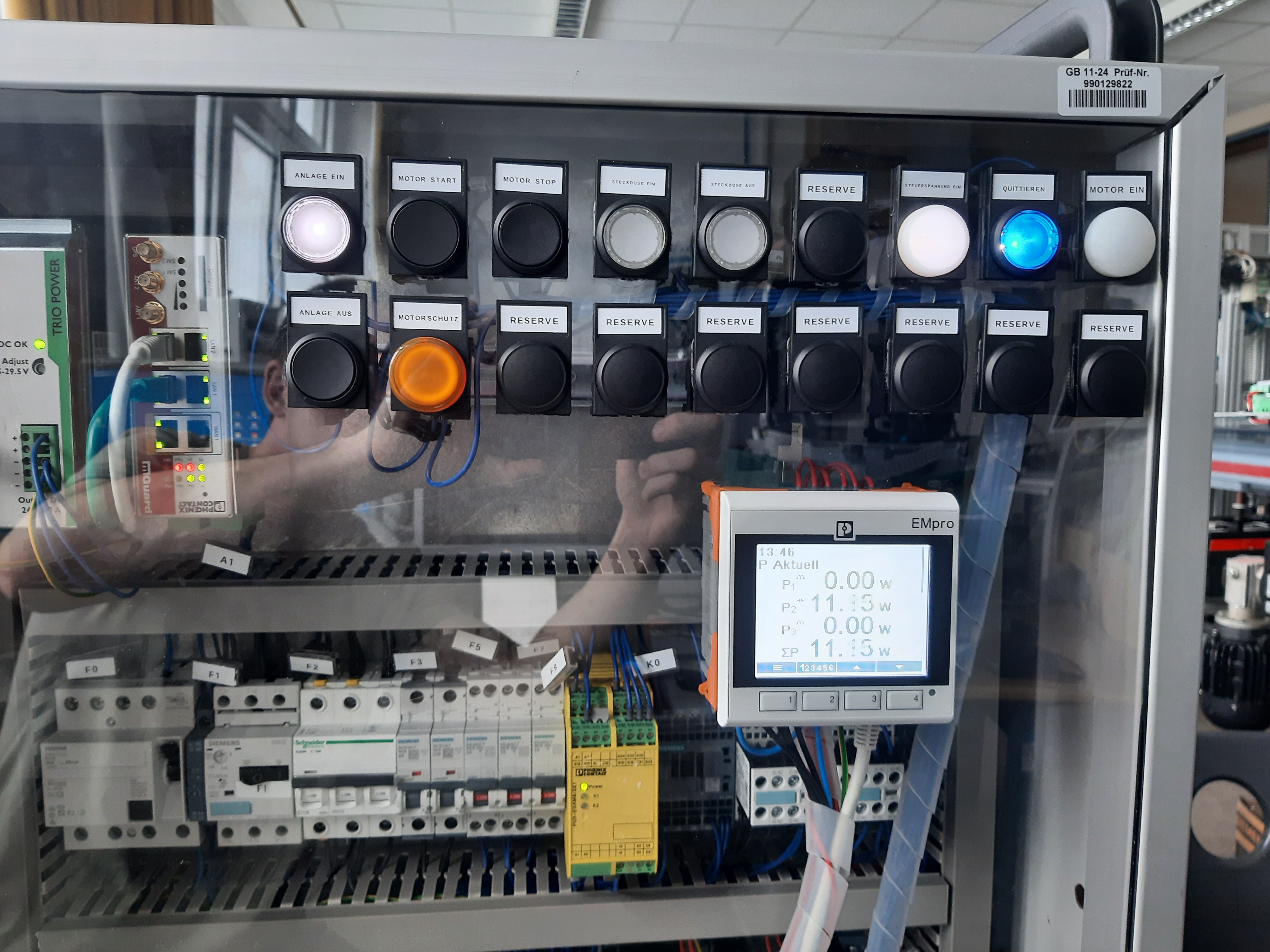
Figure: operating elements
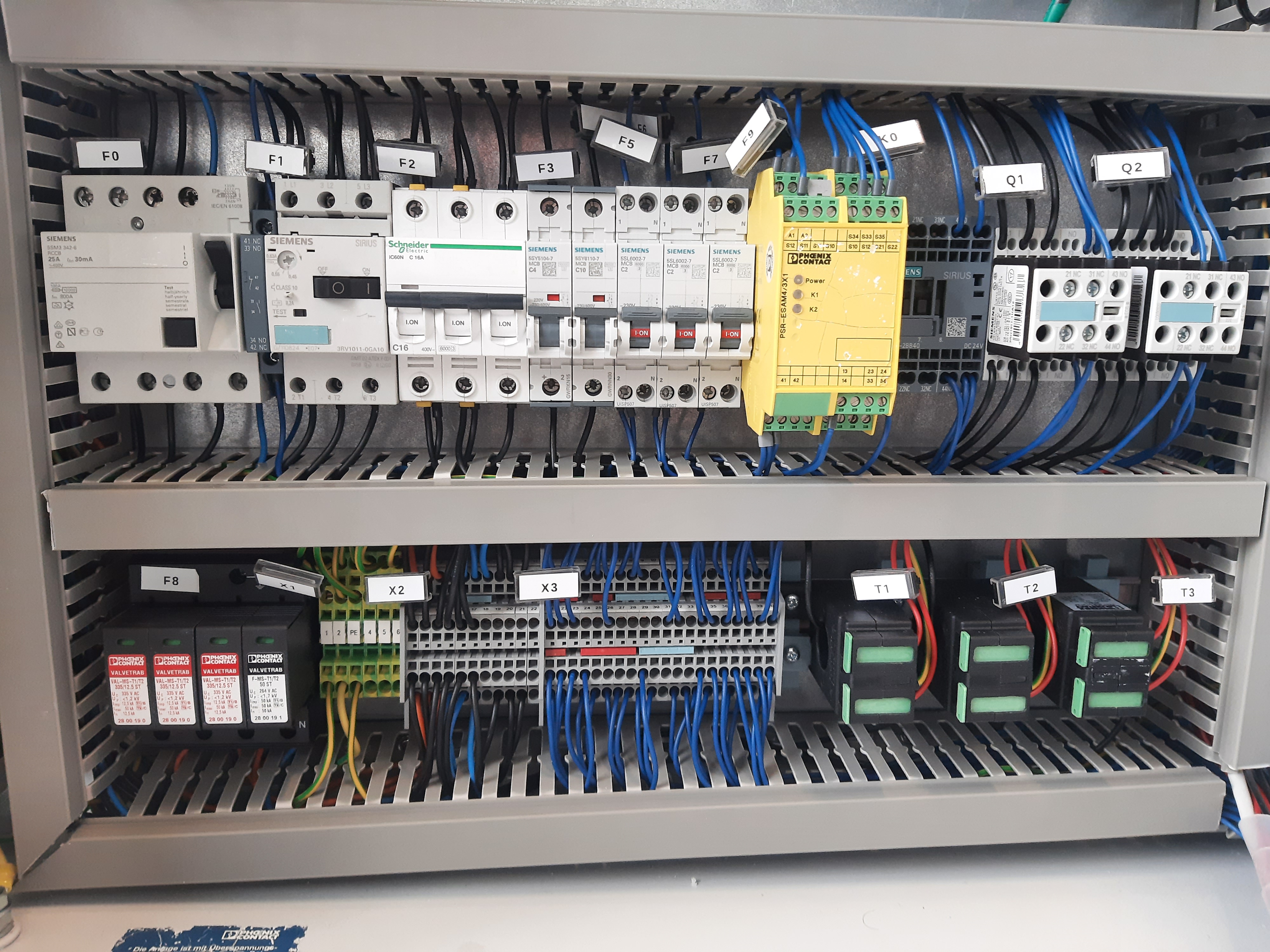
Figure: inside of the control cabinet
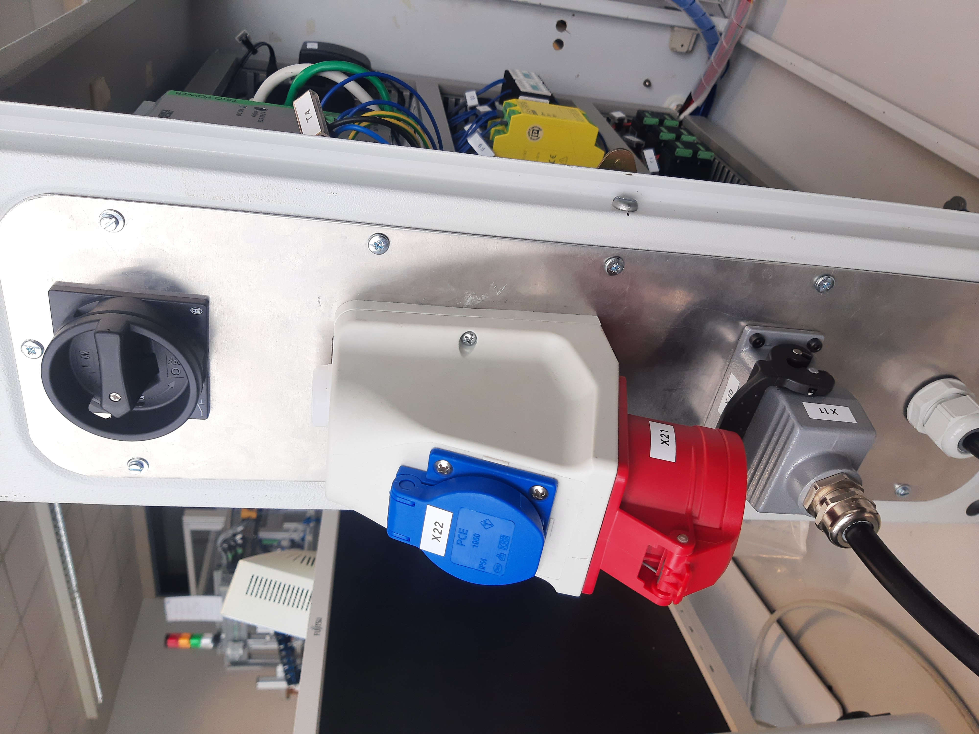
Figure: connections of the control cabinet
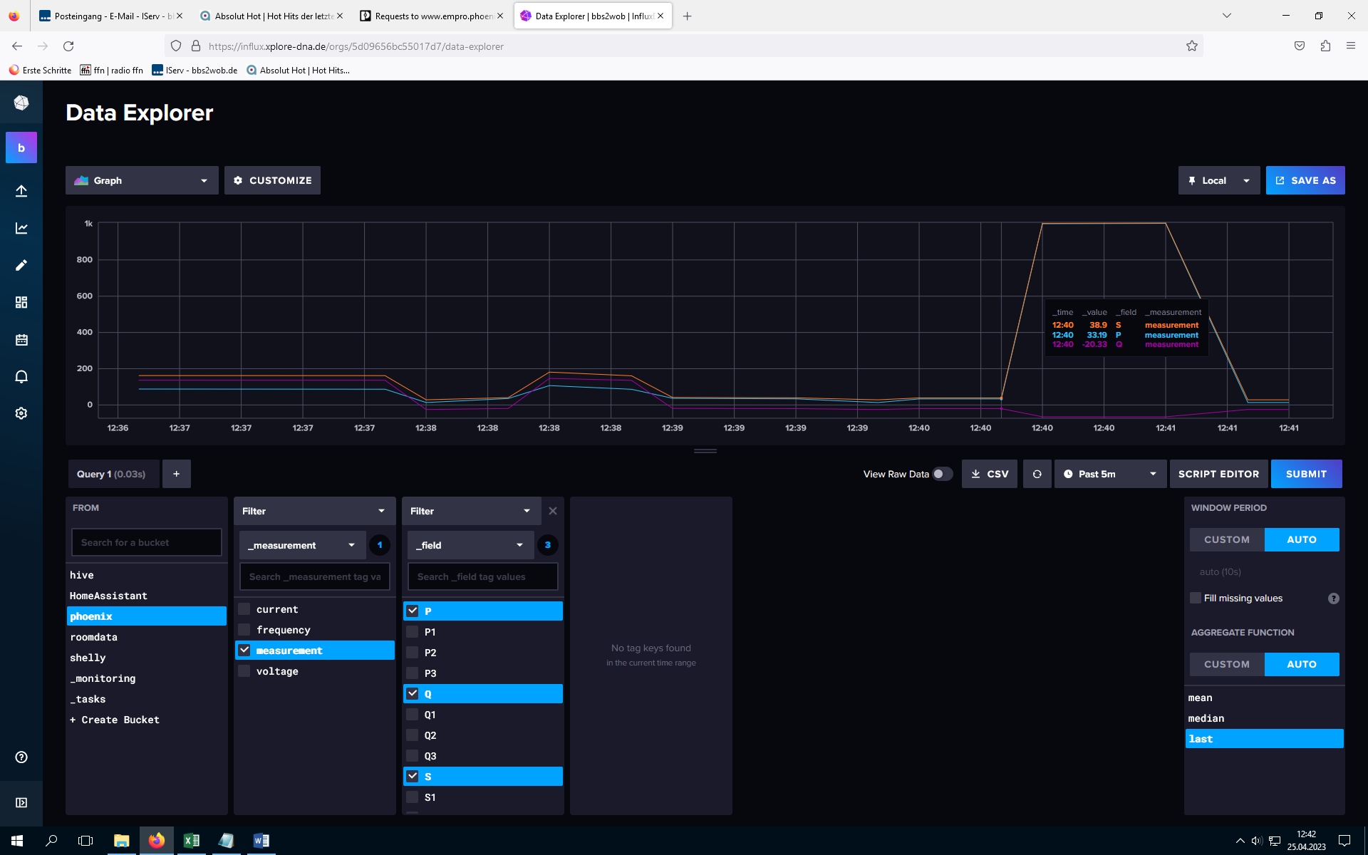
Figure: section of the database